Laboratory measurements of proppant conductivity and settling fee
Earlier than completely different proppants are utilized within the subject experiments, their conductivities and settling charges are measured within the lab. A size of reservoir core with a diameter of 10 cm is drilled from the Baikouquan formation (T1b), which is then lower into smaller plates as required by the API commonplace for measuring the long-term proppant conductivity. Every rock plate has a size of 17.7 cm, a width of three.8 cm, and a thickness of 1.8 cm. In the course of the conductivity measurement, 8 kg/m2 of proppants (silica sands or ceramics) is stuffed between a pair of rock plates, after which loaded right into a testing cell as proven in Fig. 1. After the cell is put in a urgent machine for making use of the closure strain, 2percentKCl is repeatedly flowed by the cell. At every closure strain, the strain drop throughout the cell after 50 h of KCl flooding is recorded for calculating the conductivity utilizing the Darcy’s regulation; that is repeated for closure pressures growing from 27.6 to 69.0 MPa.
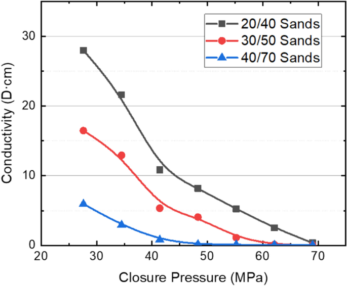
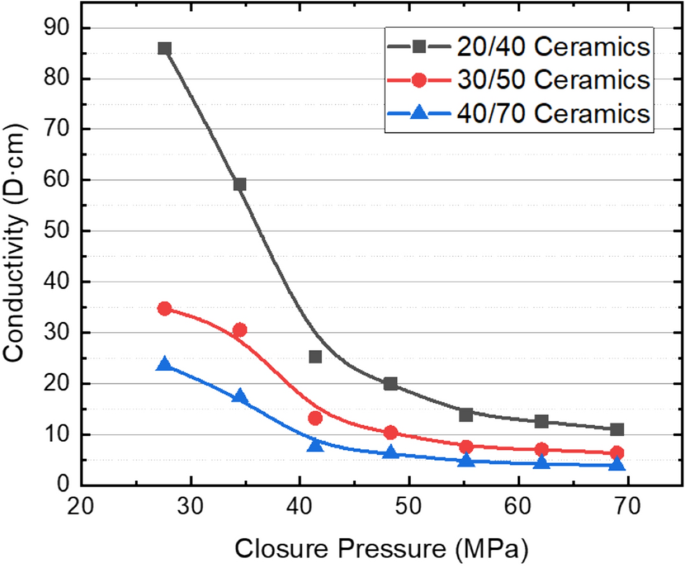
Figures 2 and 3 present the adjustments of conductivity of silica sands and ceramic proppants with completely different meshes and closure pressures in reservoir rock plates. Each figures present the proppant conductivity decreases with the proppant diameter and closure strain as recognized already. For 20/40 mesh silica sands, the conductivity decreases from 27.9 to 0.4 D cm when the closure strain will increase from 27.6 to 69.0 MPa. When the sand dimension decreases to 30/50 mesh, the propped fracture virtually loses the conductivity at 62 MPa; when the sand dimension additional decreases to 40/70 mesh, the closure strain when the propped fracture virtually loses the conductivity decreases to 48 MPa. Ceramic proppants have increased energy, higher roundness and sphericity evaluating to silica sands; due to this fact, they’ve bigger conductivity and reduces much less steeply than silica sands. At comparatively low closure pressures, the conductivity of ceramic proppants is about 3 instances of silica sands on the similar mesh. Even at a closure strain of 69 MPa, the conductivity of ceramic proppants at 40/70 mesh might be as giant as 3.5 D cm, and thus with the ability to assist hydraulic fractures open at a deep reservoir.
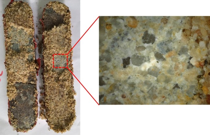
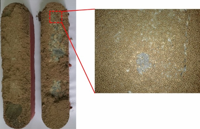
After the conductivity measurement, rock plates are taken out of the testing cell for remark. Determine 4 reveals the open plates containing silica sands after the long-term conductivity take a look at. The crushing of silica sands is sort of ubiquitous, which creates numerous superb particles plugging the propped fracture and reduces the fracture conductivity. Nevertheless, the embedment of sands into the rock plates will not be noticed, and it isn’t the explanation inflicting the discount of fracture conductivity proven in Fig. 2. Determine 5 reveals the open plates containing ceramic proppants after the long-term conductivity take a look at. In comparison with the case with silica sands, the crushing of ceramic proppants might be observed however much less frequent, which permits the propped fracture to take care of a moderation conductivity when the pore strain decreases and the closure strain will increase in the course of the manufacturing. In the meantime, after ceramic proppants are cleaned from the rock floor, small pits might be noticed because of the embedment of proppants. Nevertheless, when evaluating with the conductivity knowledge measured from the API methodology, one can discover that crushing continues to be the principle purpose inflicting the conductivity discount of the ceramic-propped fracture, though it’s much less vital than that within the sand-propped fracture.
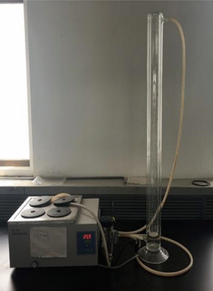
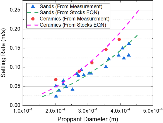
The settling fee of proppant is measured utilizing a 1-L graduated cylinder with a temperature controller as proven in Fig. 6. The cylinder has an inside diameter of fifty mm, which may decrease the collision impact from the cylinder wall when a micron-sized proppant is settling therein. In the course of the measurement, the cylinder is firstly stuffed with water; then, water is repeatedly flowing between the inside wall and outer wall of the cylinder to maintain the temperature at 25℃; after the temperature is stabilized, a proppant with a pre-determined diameter is gently positioned within the water contained in the cylinder. As soon as the proppant falls to the half-height of the cylinder and its settling fee turns into virtually secure, the settling fee is calculated utilizing the settling distance divided by the recorded time. Determine 7 reveals the measured settling charges of ceramic proppants and silica sands with completely different diameters in water, and their settling charges calculated from the Shares equation. As forecasted by the equation, the settling fee will increase with the proppant diameter and reduces with the proppant density.
Discipline experiments with completely different proppants
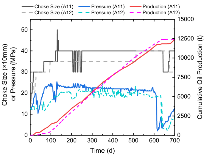
Within the Ma-131 play the place the reservoir depth is shallower than 3300 m, utilizing silica sands to utterly exchange ceramic proppants is examined in 14 horizontal wells, after which in contrast with 17 neighboring wells utilizing ceramic proppants. As might be seen from the conductivity measurement within the lab, the silica sand has a comparatively low conductivity worth evaluating to the ceramic proppant; due to this fact, when fracturing with silica sands within the subject experiments, the proppant quantity is elevated by 20% to compensate for the conductivity loss in comparison with the ceramic proppants (i.e., 1.1 instances the proppant quantity of the ceramic properly). Desk 1 reveals the fracturing parameters of a pair of neighboring wells for testing the efficiency of several types of proppants. A12 is the management properly with ceramic proppants, whereas A11 is the experimental properly with 1.1 instances the full proppant quantity of A12. Each wells have related lengths, cluster spacings, and numbers of phases and clusters. Since related pumping schedules are utilized, the water quantity used per size will increase with the proppant quantity used per size. Determine 8 reveals the manufacturing histories of each wells, the place strong curves present the choke dimension, strain, and accumulative oil manufacturing of A11, whereas dot curves reveals these of A12. Each wells are produced with related manners as might be seen from the adjustments of choke dimension. The pressures of each wells gently decay from 25 to about 20 MPa in 600 days, throughout which the accumulative oil productions are each about 12,000 t. After 600 days, pressures of each wells drop because of the aggressive flowback of neighboring wells, thus their choke sizes are diminished till neighboring wells are modified again to regular; later, pressures and productions of each wells regularly recuperate as proven in Fig. 8. In brief, no apparent change is observed when the kind of proppants is modified on this pair of neighboring wells.
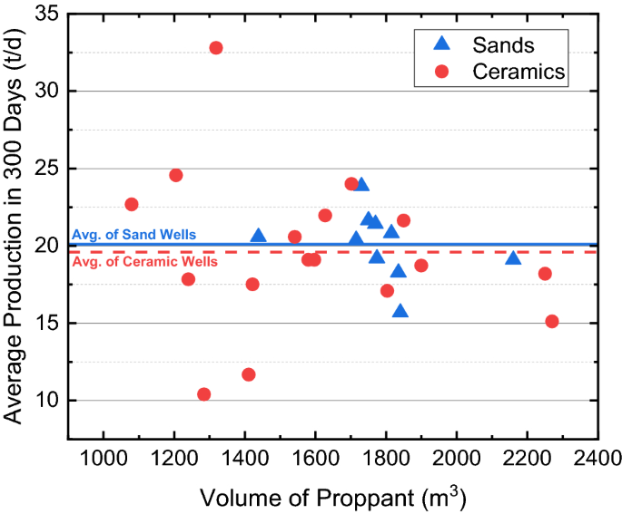
Determine 9 reveals the common each day manufacturing charges of all 31 wells within the Ma-131 play for the proppant-comparison experiments. Silica sands are utilized in 14 wells, whose manufacturing ranges from 15 to 25 t/d, with a median of 20.1 t/d; ceramic proppants are utilized in the remainder 17 wells, whose common manufacturing is nineteen.6 t/d. Within the reservoir with a depth of lower than 3300 m, the efficient closure strain is smaller than 30 MPa, and no apparent distinction is observed when ceramic proppants are changed by silica sands throughout hydraulic fracturing.
The Ma-18 play has a depth bigger than 3500 m, and the horizontal stress might be as giant as 75 MPa. In the course of the manufacturing the place the pore strain decays with time, the efficient closure strain can improve from 40 to virtually 60 MPa. Due to this fact, silica sands can not utterly exchange ceramic proppants in subject experiments; 50% sands are blended with 50% ceramics, whereas the full proppant quantity is 1.1 instances that of the pure ceramic wells. Desk 2 reveals the fracturing parameters of a pair of neighboring properly for the experiment within the Ma-18 play. B03 is the management properly with ceramic proppants, whereas B05 is the experimental properly utilizing the combination of silica sands and ceramic proppants. Each wells have related lengths, cluster spacings, and numbers of phases and clusters. Just like the properly pair proven in Desk 1, the water quantity will increase with the proppant quantity, and B05 additionally has 1.1 instances the full water quantity of B03 due to the same pumping schedules.
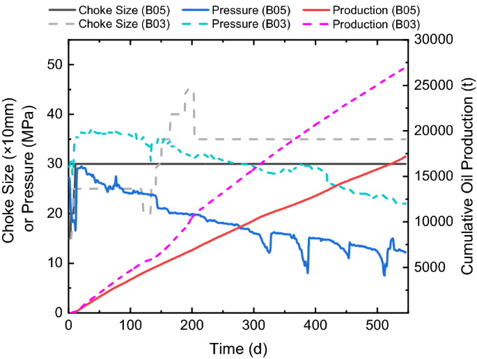
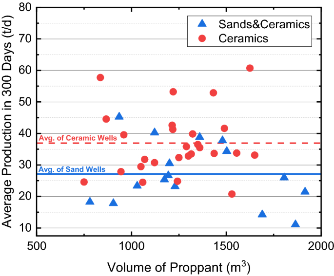
Determine 10 reveals the manufacturing histories of each wells, the place strong curves present the choke dimension, strain, and accumulative oil manufacturing of B05, whereas dot curves reveals these of B03. When 50% sands are used, each the strain and cumulative oil manufacturing scale back to 2/3 of these of the neighboring properly utilizing 100% ceramic proppants. Determine 11 additional reveals the common each day manufacturing charges of all 43 wells within the Ma-18 play for the proppant-comparison experiments. Mixtures of silica sands and ceramic proppants are utilized in 16 wells, whose manufacturing ranges from 10 t/d to 45 t/d, with a median of 27.1 t/d; pure ceramic proppants are utilized in the remainder 27 wells, manufacturing ranges from 20 to 60 t/d, with a median of 36.9 t/d. Outcomes point out that the oil manufacturing fee will increase because the reservoir pore strain will increase with depth; nevertheless, the efficient closure stress will increase extra considerably with depth, which aggravates the crushing of silica sands and the superb migrant that additional plugs the propped fracture and reduces the conductivity of the created fracture. Within the Ma-18 play the place the reservoir depth is bigger than 3500 m, silica sands can’t be used as proppants.
In abstract, laboratory measurements have proven that the settling fee of the ceramic proppant is 1–1.5 instances bigger than the silica sand, which ends up in a much less migration fee of the proppant-bank throughout the created fracture; in the meantime, the conductivity of the propped fracture by ceramic proppants is 2–5 instances of that by silica sands at closure strain lower than 55 MPa. Nevertheless, because of the limitation of laboratory measurement, proppant migration within the fracture and the conductivity of the propped fracture can’t be evaluated on the similar time; secondly, though reservoir rock samples are used within the conductivity measurement as proven in “Laboratory measurements of proppant conductivity and settling rate” part, the mimicked fracture faces are flat that ignores the affect of face roughness on proppant migration and fracture conductivity; thirdly, simulation research have additionally proven that the closure strain can have an effect on the move sample of fluid throughout the fracture with tough fracture faces and thus the fracture conductivity31. Due to this fact, subject experiments are essential to evaluating the efficiency of various proppants that may take into account the affect components ignored within the lab. In reservoirs shallower than 3300 m, wells with pure silica sands carry out equally to ones with pure ceramic proppants, which signifies that the manufacturing loss because of the diminished fracture conductivity might be compensated by the elevated migration fee of proppants when the cheaper silica sands are utilized; due to this fact, the silica sands are promising in these shallow reservoirs in future improvement. In reservoirs deeper than 3500 m, oil manufacturing might be decreased by 30% when 50% ceramic proppants are changed by silica sands; this agrees with the outcomes of conductivity measurements and additional confirms that conductivity is the controlling think about these deep reservoirs. A sooner migration fee of silica sands in the meantime results in a narrower width of the propped fracture, which is extra prone to the closure strain. Due to this fact, high-strength proppants are nonetheless the most suitable choice for deep reservoirs in Mahu.
Discipline experiments with completely different fracture spacing
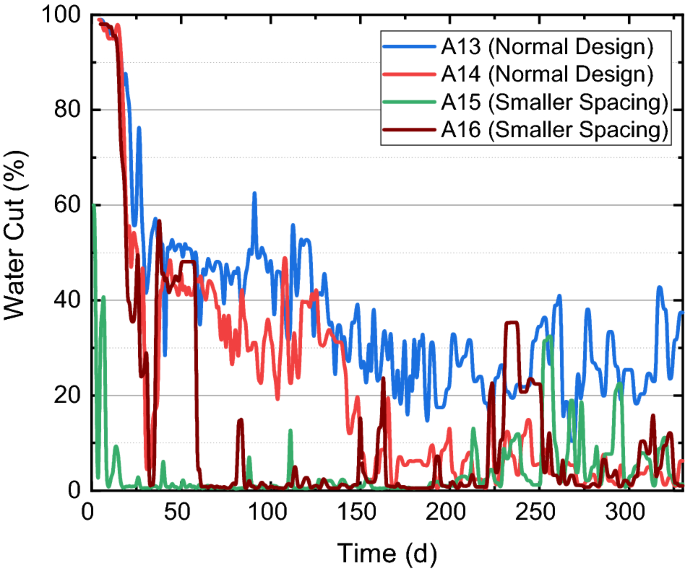
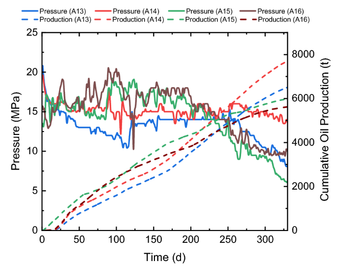
Lowering the fracture spacing can worsen the stress shadow impact and improve the closure stress that impacts the conductivity of silica sands. Apart from, when the “fracture swarm” varieties, the fracture spacing might be considerably smaller than the designed one32. Due to this fact, the affect of fracturing spacing is evaluated for wells utilizing silica sands which might be delicate to the change of stress within the Ma-131 play. Desk 3 reveals the fracturing parameters of 4 neighboring wells for evaluating the affect of fracture spacing on the conductivity of sand-propped fractures. A13 and A14 are management wells with the traditional design as ones proven in Desk 1, whereas A15 and A16 are experimental wells with smaller fracture spacings. The cluster variety of every properly is doubled inside one fracturing stage, however volumes of proppants and water per stage nonetheless stay the identical to maintain the funding per properly virtually unchanged. As might be seen from this desk, the proppant quantity per size are all about 1.2 m3/m and the water quantity per size are all about 20 m3/m; nevertheless, the full proppant quantity per cluster decreases from 40 to twenty m3/m, and the full water quantity per cluster decreases from 600 to 350 m3/m because the cluster per stage will increase from 2 to three within the experimental wells.
Determine 12 reveals adjustments of the water lower of 4 wells. When the fracture spacing decreases and extra fractures are designed inside one fracturing stage, the fracturing fluid per cluster decreases, and the leak-off of fracturing fluid into the reservoir rock will increase. These end in smaller water lower and thus a smaller flowback ratio in the course of the manufacturing in A15 and A16. Determine 13 reveals the manufacturing histories of 4 wells, the place strong curves present the strain and dot curves present the cumulative oil manufacturing of them. In contrast with A13 and A14, A15 and A 16 have comparatively excessive productions within the first 200 days, however their pressures decay sooner which makes their productions decrease than wells with regular designs after one yr of manufacturing. When the fracture spacing decreases, the reservoir rock is healthier uncovered to the created fracture community, which contributes to the manufacturing enhancement on the early time of manufacturing. Nevertheless, because the proppant quantity is stored fixed per unit size, created fractures can’t be properly propped when the fracture spacing decreases; moreover, the lower of fracture spacing additionally will increase the closure stress, particularly when the pore strain decays with oil manufacturing, which aggravates the crushing of silica sands and the lower of fracture conductivity. This group of subject experiments signifies that enough sands are crucial for every fracture (no less than 30 m3) to acquire an financial manufacturing fee when the fracture spacing decreases to fifteen m or smaller within the Ma-131 play.
Discipline experiments with completely different fracturing fluids
The crosslinked guar is 3 instances the worth of the slickwater, and its residuals can cowl the fracture face and plug the propped fractures that reduces the properly productiveness. It has been broadly accepted that the crosslinked guar has a very good proppant-carrying potential, and thus can generate lengthy and slender propped fractures. When the slickwater is used, a big pumping fee is required to compensate the lack of proppant-carrying potential; it probably generates quick and extensive propped fractures (particularly within the near-wellbore area), and might create a fancy fracture community in weakly-consolidated reservoirs or reservoirs with pure fractures. The Mahu reservoir has a comparatively giant permeability that requires the propped fractures to have a big conductivity to match; in the meantime, the reservoir with a thickness of some tens of meters has little demand for vertical supporting of proppants. Due to this fact, slickwater generally is a promising possibility, and thus it’s evaluated by subject experiments.
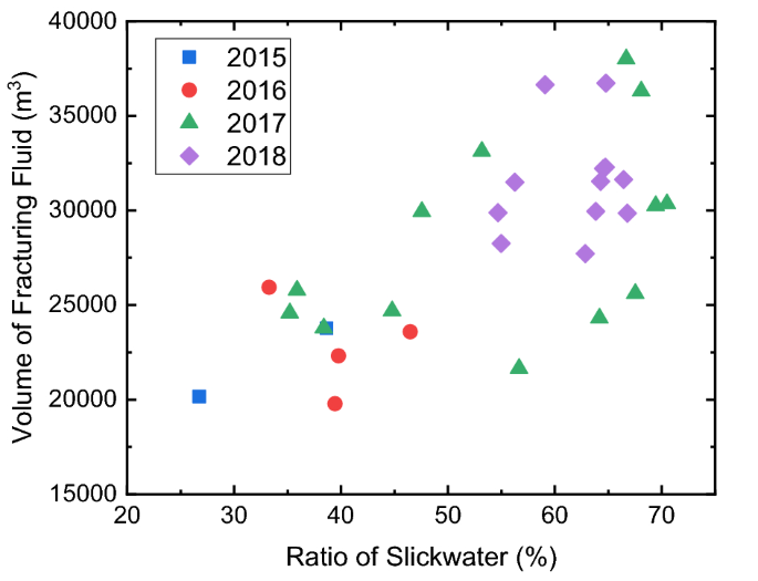
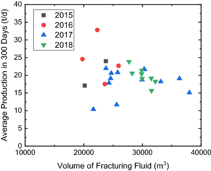
From 2015 to 2018, the slickwater ratio is regularly elevated, and it’s anticipated to judge if slickwater can utterly exchange the crosslinked guar within the Mahu reservoir. Determine 14 reveals the cross plot of the slickwater ratio and the full quantity of fracturing fluid of 31 experimental wells in these 4 Years. Because the friction reducer added within the slickwater can scale back greater than 70% of friction strain of fluid flowing contained in the wellbore, a big pumping fee might be utilized throughout hydraulic fracture. Due to this fact, when the ratio of slickwater will increase, the full quantity of the fracturing fluid used per properly additionally will increase, and the depth of fracturing fluid can attain 20 m3/m. Determine 15 reveals the cross plot of the full quantity of fracturing fluid and the common annual manufacturing of experimental wells in these 4 years. Though the amount of fracture fluid is considerably elevated, no apparent enhancement of the oil manufacturing is noticed. Because the quantity of proppants per cluster stays the identical, the potential improve of fracture quantity doesn’t result in a rise of the propped fracture quantity. When the slickwater ratio will increase, a big pumping fee can forestall the proppant plugging in the course of the operation, however no manufacturing enhancement needs to be anticipated with out growing the proppant quantity per cluster.
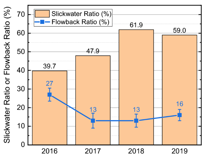
Determine 16 reveals the change of common slickwater ratio and flowback ratio in 4 years. In contrast with the crosslinked guar, slickwater is considerably much less viscous and has a big leak-off coefficient. When the fracturing fluid leaks off into the reservoir rock, the created fracture can shut and be properly propped on the closure strain. This may doubtlessly forestall the flowback of proppant and retain the conductivity of the propped fracture throughout oil manufacturing. In all, decreasing the utilization of the crosslinked guar and growing the slickwater ratio can scale back the operation price with out clearly affecting the migration of proppants and the properly productiveness. Due to this fact, changing the crosslinked guar with slickwater is beneficial for future fracturing designs.


